The Warp 10 MQTT plugin allows you to easily subscribe to TheThingNetwork LoraWan messages. Connecting IoT has never been so easy.

A long time ago, at SenX, we helped to kickstart The Things Network. We received our starter kit and left it a few months in the dust because no one had time to play with it. Friday, ending a big project, I really wanted to power everything and connect it to Warp 10 in just ONE day.
But… It didn't work as expected! To save you lots of pain, I will explain here all the hardware update steps you need to go through to get everything working. Then I will explain the easy part, the Warp 10 MQTT connection.
| Learn how to build a BeerTender Dashboard with Warp 10 and Grafana! |
Day 1: The Gateway
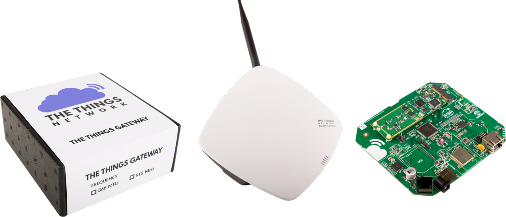
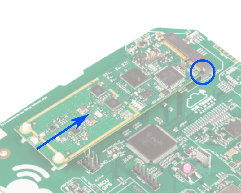
First, open it and make sure the LoRa module is correctly inserted in its connector. The PCB must touch the connector in the blue circle below :
Then upgrade the firmware with the latest stable version. The update procedure is here. You need a FAT32 formatted micro SD card. Once done, reboot the system, and register your gateway. Johan Stokking also made a short video on YouTube to help you. You should have 4 LEDs turned on, and you can check the gateway status on this local URL: http://things-gateway.local/info. Once the gateway was working, I spent the remaining hours reading the doc and setting up the first The Things UNO.
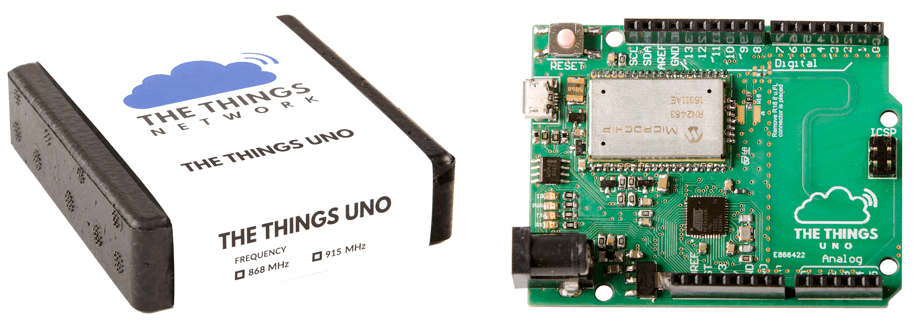
Day 2: The Things UNO boards
I have five of these Microchip RN2483 boards:
The RN2483 is a LoRaWAN Class A protocol stack. So it has its own firmware. And its own bugs… I spent one more day stuck with joining problems. With exactly the same example program, two boards were sending packets, but not the third one. Both were on my desk, 5 m away from the gateway, it could not be a coverage problem. After following this Johan Stokking tutorial on YouTube, my Arduino logs looked like:
Sending: mac join otaa Response is not OK: no_free_ch
Send join command failed
Sending: mac join otaa Join not accepted: denied
Check your coverage, keys and backend status.
Sending: mac join otaa Join not accepted: denied
Check your coverage, keys and backend status.
You need to update the RN2483 on your The Things UNO. To do so, load the PassThrough example from the TheThingNetwork Arduino examples. It enables direct communication between the Microchip device and your computer. Then, download the latest RN2483 firmware from here. I took the 1.0.5 firmware and the LoRa Development Suite for Linux.
You don't need root access to install the LoRa Development Suite for Linux: make the run file executable, then execute it as a normal user. Uncheck the Docker Server Image and Java Redistributable RE8. I assume you already have openjdk-8-jre-headless installed on your system. This software also has a bug that prevents you from updating the firmware… You need to create three XML files on your system to avoid a Java exception. These XML files must point to an existing directory on your system, for example:
<?xml version="1.0" encoding="UTF-8" standalone="no"?>
<!DOCTYPE map SYSTEM "http://java.sun.com/dtd/preferences.dtd">
<map MAP_XML_VERSION="1.0">
  <entry key="FilePath" value="/home/"/>
</map>
Create missing directories:
mkdir -p ~/.java/.userPrefs/dfu
mkdir -p ~/.java/.userPrefs/fed
mkdir -p ~/.java/.userPrefs/toplevel
Then edit these three files to paste the valid XML described upper:
vim ~/.java/.userPrefs/dfu/prefs.xml
vim ~/.java/.userPrefs/fed/prefs.xml
vim ~/.java/.userPrefs/toplevel/prefs.xml
Unplug and replug your board, launch the Microchip software:
cd ~/Microchip/LoRaSuite/Applications/LoRaDevUtility
java -jar LoRaDevUtility.jar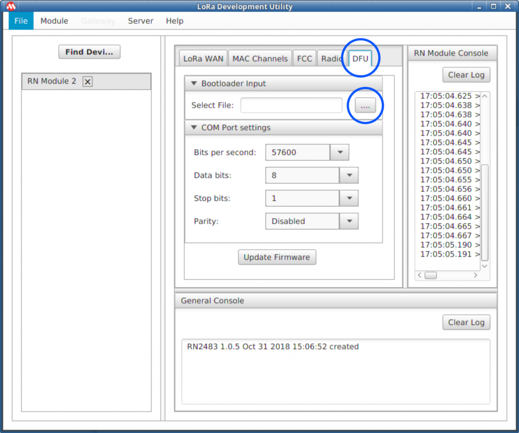
You can now go to the DFU tab, then press the select file button (the one which won't work if you do not put the XML files before). Select the combined/RN2483_Parser.production.unified.hex file you extracted from the microchip zip file. Click update, and loop until all your The Things UNO boards are up-to-date!
| Discover the Raspberry Beer'o'meter |
Device to MQTT
Follow the Johan Stokking tutorial on YouTube to get your device ID and send your first packets. My program is the example slightly modified to send a decreasing counter:
#include <TheThingsNetwork.h>

// Set your AppEUI and AppKey
const char *appEui = "xxxxxxxxxxxxxxxx";
const char *appKey = "yyyyyyyyyyyyyyyyyyyyyyyyyyyyyyyy";

#define loraSerial Serial1
#define debugSerial Serial
#define freqPlan TTN_FP_EU868

TheThingsNetwork ttn(loraSerial, debugSerial, freqPlan);

void setup() {
  loraSerial.begin(57600);
  debugSerial.begin(9600);

  // Wait a maximum of 10s for Serial Monitor
  while (!debugSerial && millis() < 10000)
  ;

  debugSerial.println("-- STATUS");
  ttn.showStatus();
  debugSerial.println("-- JOIN");
  ttn.join(appEui, appKey);
}

unsigned char counter = 255;

void loop() {
  debugSerial.println("-- LOOP");

  // Prepare payload of 1 byte
  byte payload[1];
  payload[0] = counter--;

  // Send it off
  ttn.sendBytes(payload, sizeof(payload));

  delay(10000);
}
You should have your data visible in your application, in TheThingsNetwork console. It is time to test MQTT. First, install an MQTT client on your computer:
sudo apt install mosquitto-clientsTo read the MQTT stream from TheThingsNetwork, you need to use your application name as user, and your application access key as the password. You can find it in the console too:
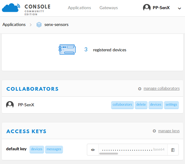
You can now test with mosquitto. TheThingNetwork API is documented here. These commands subscribe to the senx-sensor1 uplink topic.
mosquitto_sub -h eu.thethings.network -P "MYSECRETKEY" -u "senx-sensors" -d -t "senx-sensors/devices/senx-sensor1/up"Every 10s, I receive a JSON message with a payload:
{
  "app_id": "senx-sensors",
  "dev_id": "senx-sensor1",
  "hardware_serial": "0004A30B001C4258",
  "port": 1,
  "counter": 476,
  "payload_raw": "3A==",
  "metadata": {
    "time": "2019-02-18T16:38:06.456817974Z",
    "frequency": 868.5,
    "modulation": "LORA",
    "data_rate": "SF7BW125",
    "airtime": 46336000,
    "coding_rate": "4/5",
    "gateways": [
      {
        "gtw_id": "lora-senx",
        "gtw_trusted": true,
        "timestamp": 3224012587,
        "time": "2019-02-18T16:38:06Z",
        "channel": 2,
        "rssi": -60,
        "snr": 7.25,
        "rf_chain": 1,
        "latitude": 48.442142,
        "longitude": -4.4144206,
        "altitude": 2,
        "location_source": "registry"
      }
    ]
  }
}
payload_raw is the base64 encoded payload. Everything is working as expected after two days of struggling with hardware… Time for the easy part.
MQTT to Warp 10 with MQTT plugin
Warp 10 has an MQTT plugin. We did it last year for a customer. It is time to use it again.
git clone "https://github.com/senx/warp10-plugin-mqtt.git"
cd warp10-plugin-mqtt
./gradlew shadowJar
# replace destination by your Warp 10 lib directory
cp build/libs/warp10-plugin-mqtt-*.jar ~/warp10/lib/
How does it work? As you know, MQTT is a publish-subscribe based messaging protocol. It works on top of the TCP/IP protocol. There is no real standard for the message content though.
The idea behind the Warp 10 MQTT plugin is very close to the TCP/UDP/HTTP plugins we already provided with Warp 10 2.0. Each packet is crunched by a WarpScript macro, everything configured in a set of WarpScripts!
First, edit your Warp 10 configuration file to add the following lines:
//
// Load the MQTT plugin
//
warp10.plugin.mqtt = io.warp10.plugins.mqtt.MQTTWarp10Plugin

//
// mqtt options: the home directory of WarpScript MQTT handlers
//
mqtt.dir = ${standalone.home}/mqtt

//
// mqtt options: scan changes in the directory every 10000ms.
//
mqtt.period = 10000

//
// usefull to have the STDOUT function
//
warpscript.extension.debug=io.warp10.script.ext.debug.DebugWarpScriptExtension
The scripts you will place in the MQTT subdirectory will be reloaded after 10s if their size has changed. You can now restart Warp 10. In a terminal, watch the Warp 10 logs, it will be useful to check STDOUT output:
cd myWarp10path/bin./warp10-standalone.sh restart
tail -F ../logs/warp10.log
Time for the easiest part: subscribe to topics, and attach a macro to process the messages. Go into your MQTT directory, and create a new test.mc2 file. Edit it with your favorite WarpScript IDE. Here is an example:
// subscribe to the topics, attach a warpscript macro
// callback to each message. the macro reads
// TheThingNetwork message to extract the first byte
// of payload, the server timestamp, and the device id.

'Loading MQTT TTN Warpscript' STDOUT
{
  'host' 'eu.thethings.network'
  'port' 1883
  'user' 'senx-sensors'
  'password' 'MYSECRETKEY'
  'clientid' 'Warp10'
  'topics' [
    'senx-sensors/devices/senx-sensor1/up'
    'senx-sensors/devices/senx-sensor2/up'
    'senx-sensors/devices/senx-sensor3/up'
  ]
  'timeout' 20000
  'parallelism' 1
  'autoack' true
  'macro' <%
    //in case of timeout, the macro is called to flush buffers, if any, with NULL on the stack.
    'message' STORE
    <% $message ISNULL ! %>
    <%
      'message' STORE
      $message MQTTPAYLOAD 'ascii' BYTES-> JSON-> 'TTNmessage' STORE
      $TTNmessage 'payload_raw' GET OPB64-> 0 GET 'countervalue' STORE
      $TTNmessage 'metadata' GET 'time' GET TOTIMESTAMP 'ts' STORE
      $TTNmessage 'dev_id' GET 'sensorID' STORE
      $message MQTTTOPIC ' ' +
      $sensorID + ' ' +
      $ts ISO8601 + ' ' +
      $countervalue TOSTRING +
      STDOUT // print to warp10.log
    %> IFT
  %>
}
Save it, and wait. Look at the log tail. After a few seconds, the first messages from the two connected boards on my desk appeared:
Loading MQTT TTN Warpscript
senx-sensors/devices/senx-sensor1/up senx-sensor1 2019-02-18T21:08:55.118861Z 112
senx-sensors/devices/senx-sensor2/up senx-sensor2 2019-02-18T21:08:59.324649Z 62
senx-sensors/devices/senx-sensor2/up senx-sensor2 2019-02-18T21:09:11.343120Z 63
senx-sensors/devices/senx-sensor1/up senx-sensor1 2019-02-18T21:09:12.343001Z 113
senx-sensors/devices/senx-sensor2/up senx-sensor2 2019-02-18T21:09:23.461037Z 64
senx-sensors/devices/senx-sensor1/up senx-sensor1 2019-02-18T21:09:29.467510Z 114
senx-sensors/devices/senx-sensor2/up senx-sensor2 2019-02-18T21:09:35.577162Z 65
senx-sensors/devices/senx-sensor1/up senx-sensor1 2019-02-18T21:09:46.592010Z 115
senx-sensors/devices/senx-sensor2/up senx-sensor2 2019-02-18T21:09:47.696662Z 66
senx-sensors/devices/senx-sensor2/up senx-sensor2 2019-02-18T21:09:59.913020Z 67
In the Warpscript macro, I can push every datapoints in a Warp 10 instance, or store them in RAM with the Warp 10 SHM extension: it is really the easiest part of the job! If you want a custom hosting solution for your IoT data, contact us.
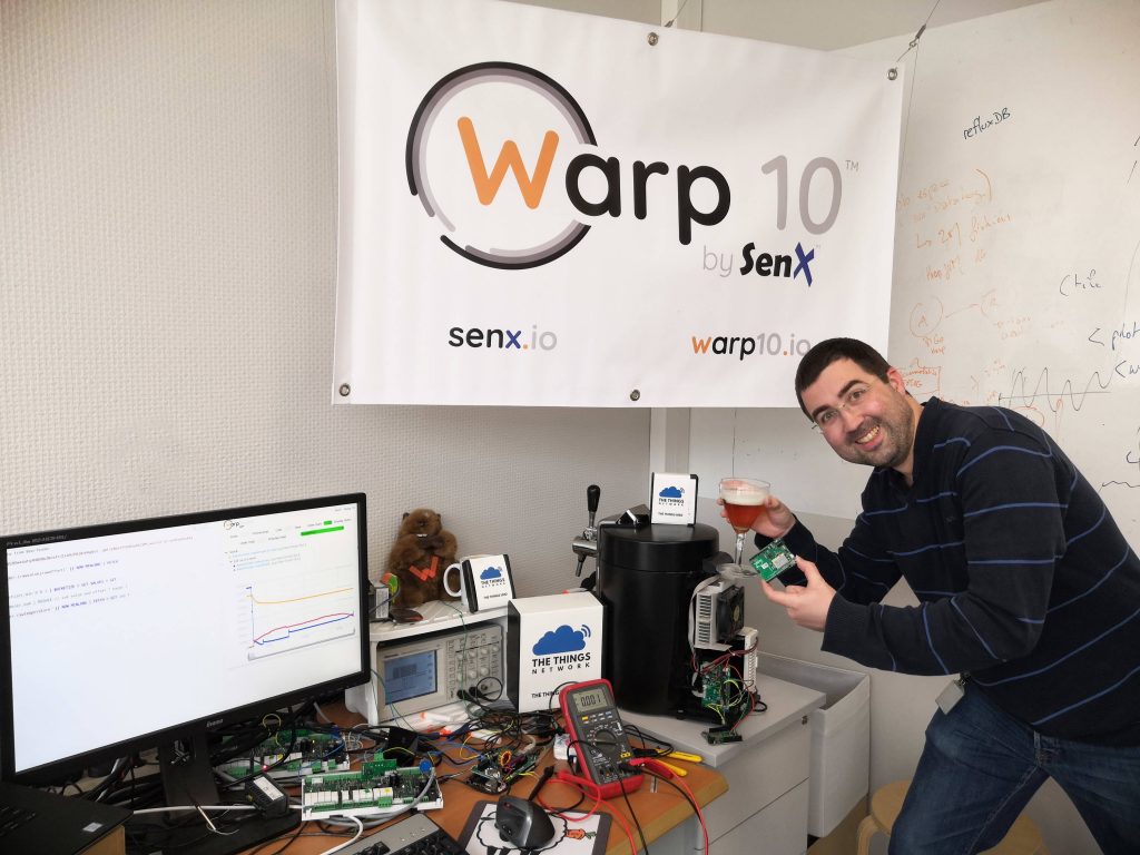
Day 3: Connecting BeerTender…
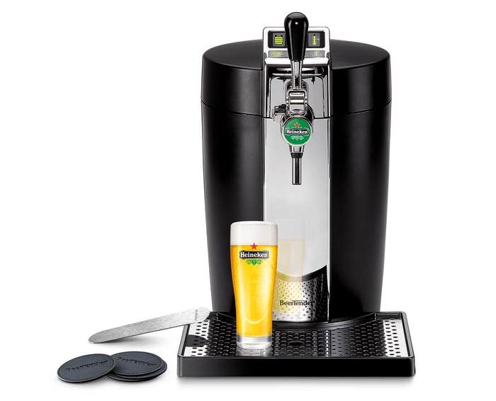
Two days to deal with the buggy lower layer firmware, 20 minutes to setup the Warp 10 MQTT plugin, it is time to go further. In our office, we have a Krups BeerTender. This is really not an IoT device, but there are two sensors inside. One for temperature, one for the weight of the beer barrel. For fun, it could be nice to be able to detect the barrel change and correlate SenX team beer consumption to… I don't know yet. Moreover, the gauge on our old BeerTender turned completely wrong, it displays full when the barrel is empty. Maybe it is a calibration problem, maybe it is a hardware problem. Anyway, I love electronics challenges.
As expected, finding the schematic is impossible. It is not really open-source hardware. Intuitively, the temperature sensor is a low-cost variable resistor (an NTC), and the weight sensor a strain gauge.
The beer temperature channel
This is the easiest one. As I expected, the NTC is continuously powered in a simple resistor divider. It is easy to read the voltage with an Arduino.
The barrel weight channel
This strain gauge sensor is rather complex, but keep in mind that a general microcontroller can only manage voltages or digital signals. So, there must be somewhere a rather complex input stage that will ultimately deliver a voltage to the microcontroller. Or maybe a digital signal, SPI, or I2C.
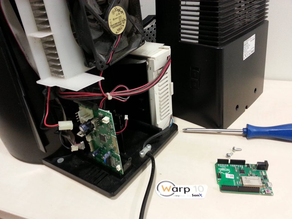
Tear Down
Tearing down is easy. Two screws, a few connectors to remove. Good surprise: It is a class II power supply, so no ground problem when I will connect an oscilloscope or my computer to the system.
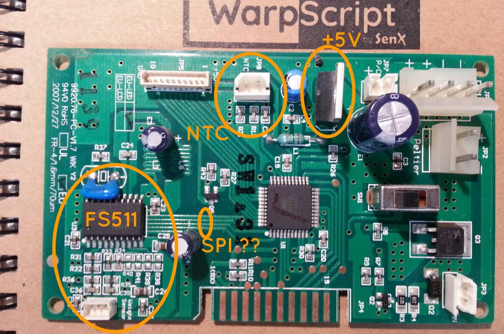
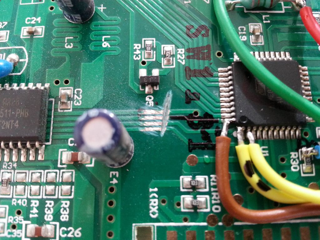
- Good guess, the temperature sensor is a basic NTC. We see the resistor divider and a little filter capacitor. Reading this will be easy.
- Good surprise, the power supply is a good old 7805. No need to recreate +5V for the Arduino board, just take it there.
- The strain gauge controller is an FS511. The datasheet is available. I don't know anything about this circuit. It is an 18-bit SPI ADC. With a multimeter and the FS511 pin configuration, it is easy to follow each SPI wire to the microcontroller.
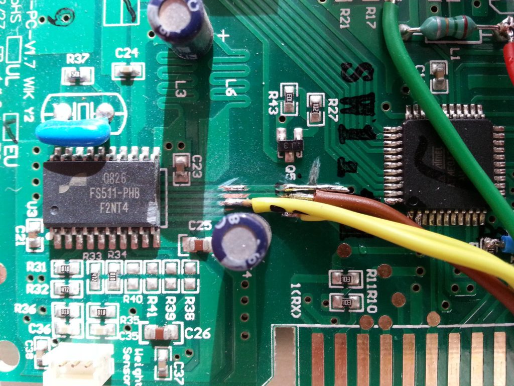
Pick useful connections
It is time to sold wires on the interesting nets:
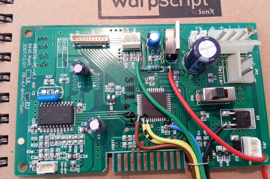
- Black: Ground
- Red: +5V
- Green: NTC voltage
- Brown: Slave Data In
- Yellow: Chip Select
- Blue: Slave Data Out
- Yellow with black marks: Clock
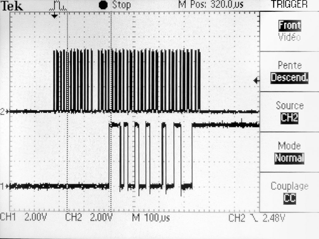
FS511 is a rather complex piece of silicon. The ADC could be configured to read the bridge sensor, but also several offsets. Spying Data Out and Clock may not be enough, we don't know exactly what is measured. Looking at the oscilloscope, there are 10 measures per second, but sometimes another one with a different result, maybe an offset. The clock is either really slow (70µs period, or really fast (12µs period, 1µs true, 11µs false). It seems the microcontroller does some software SPI for the first 4 bits, then regular hardware for the last 3 bytes.
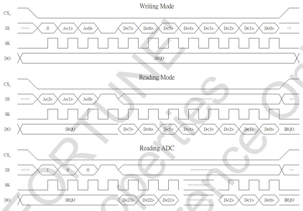
Decoding this will be hard too! 4 bit address then 24 bits data is not a common pattern.
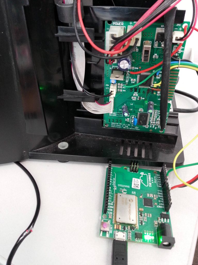
Is the Arduino UNO fast enough?
1µs spikes of the clock are troublesome… To be sure, I made a little loop sketch on The Things Arduino UNO:
#define output 0

void setup() {
  // put your setup code here, to run once:
  pinMode(output,OUTPUT);
}

void loop() {
  digitalWrite(output,LOW);
  digitalWrite(output,HIGH);
}
The result raises a huge red alarm in my brain: period is 7µs… I need a 20 times faster microcontroller to decode the signal! In my mind, there are two possible solutions to get around:
- Develop another program with a faster DSPic33F board I have, put it between the BeerTender board and the UNO LoraWan board.
- Cut everything between the existing microcontroller and the FS511. It means reading the barrel weight information value myself, and perfectly understanding the FS511.
The first one is not feasible by everyone. I'm going to try the second one.
Before going further, it is important to get a glimpse at the used configurations of FS511. There is no magic behind it, I used an oscilloscope to capture Clock and Din during the system boot. I do not have any logic analyzer with me.
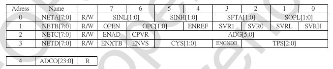
| Address 0 | 0x88 or 0xF4, change every 2 seconds |
| Address 1 | 0xDC, fixed on boot |
| Address 2 | 0x93, fixed on boot |
| Address 3 | 0x55, fixed on boot |
Time to cut the wires on the board to rewire them on the Arduino. If the BeerTender software is well done, the weight measurement is independent of the temperature control loop.
Little mistake: there is no need to cut the Dout line. Let it as it is, the pullup is already on the board.
Read sensor values
Now it is time to try to read something from the strain gauge. I am going to do software SPI all along, so I can wire everything on The Things UNO, no matter the pin number. Just avoid D0 and D1, used by LoraWan stack.
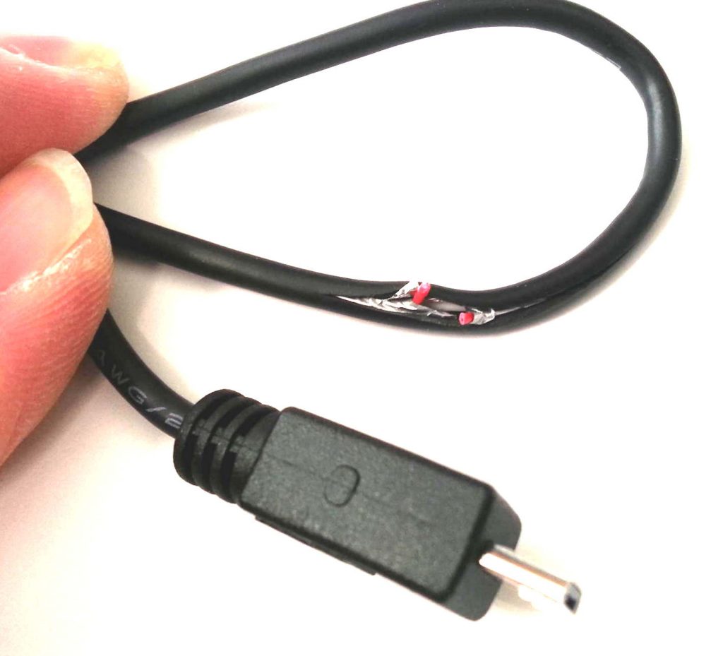
PRO TIP: The Lora UNO board will be powered by the BeerTender +5V. So… use a special micro USB Cable that will not inject the +5V of your computer inside the board! Voltages will be slightly different, and this is a risk for your beloved computer.
I will do what BeerTender did: measure offset during one second, value during one second. As the convergence time are pretty slow, I will measure every 100ms, ignore the 5 first samples, do a mean with the 5 next ones, store the result.
LoRaWan is an open network. I have to keep bandwidth for everyone. I will send results every 20s, with a 10 byte payload:
struct rawResultType{
  unsigned long offset;
  unsigned long value;
  unsigned short temperature;
};
The payload will be a mean of the 10 previous samples.
The full code
Click to see Arduino Code
#include <TheThingsNetwork.h>

// Set your AppEUI and AppKey
const char * appEui = "70B3D57ED0017ECA";
const char * appKey = "MY APP KEY";

#define loraSerial Serial1
#define debugSerial Serial
// Replace REPLACE_ME with TTN_FP_EU868 or TTN_FP_US915
#define freqPlan TTN_FP_EU868

const int TemperatureAnalog = A0;

//yellow with black dots
#define SPIclock 7
//yellow
#define SPIcs 6
//blue slave data out
#define SPImiso 5
//brown slave data in
#define SPImosi 4
#define SPIcycleClock digitalWrite(SPIclock, HIGH);

digitalWrite(SPIclock, LOW) TheThingsNetwork ttn(loraSerial, debugSerial, freqPlan);

void setup() {
  loraSerial.begin(57600);
  debugSerial.begin(9600);

  //setup the SPI bus:
  pinMode(SPIclock, OUTPUT);
  digitalWrite(SPIclock, LOW);
  pinMode(SPIcs, OUTPUT);
  digitalWrite(SPIcs, HIGH);
  pinMode(SPImiso, INPUT);
  pinMode(SPImosi, OUTPUT);
  digitalWrite(SPImosi, LOW);

  // Wait a maximum of 10s for Serial Monitor
  while (!debugSerial && millis() < 10000) continue;

  debugSerial.println("-- STATUS");
  ttn.showStatus();
  debugSerial.println("-- JOIN");
  ttn.join(appEui, appKey);
  debugSerial.println("-- init the strain gauge ADC");
  sendFS511(0, 0xF4);
  sendFS511(1, 0xDC);
  sendFS511(2, 0x93);
  sendFS511(3, 0x55);
}

void sendFS511(unsigned char address, unsigned char data) {
  digitalWrite(SPIcs, LOW);
  digitalWrite(SPImosi, LOW);

  // first bit is 0;
  SPIcycleClock;
  digitalWrite(SPImosi, (address & 2) != 0 ? HIGH : LOW);
  SPIcycleClock;
  digitalWrite(SPImosi, (address & 1) != 0 ? HIGH : LOW);
  SPIcycleClock;
  digitalWrite(SPImosi, LOW);
  //fourth bit is 0;
  SPIcycleClock;
  digitalWrite(SPImosi, (data & 0x80) != 0 ? HIGH : LOW);
  //faster than a loop...
  SPIcycleClock;
  digitalWrite(SPImosi, (data & 0x40) != 0 ? HIGH : LOW);
  //faster than a loop...
  SPIcycleClock;
  digitalWrite(SPImosi, (data & 0x20) != 0 ? HIGH : LOW);
  //faster than a loop...
  SPIcycleClock;
  digitalWrite(SPImosi, (data & 0x10) != 0 ? HIGH : LOW);
  //faster than a loop...
  SPIcycleClock;
  digitalWrite(SPImosi, (data & 0x8) != 0 ? HIGH : LOW);
  //faster than a loop...
  SPIcycleClock;
  digitalWrite(SPImosi, (data & 0x4) != 0 ? HIGH : LOW);
  //faster than a loop...
  SPIcycleClock;
  digitalWrite(SPImosi, (data & 0x2) != 0 ? HIGH : LOW);
  //faster than a loop...
  SPIcycleClock;
  digitalWrite(SPImosi, (data & 0x1) != 0 ? HIGH : LOW);
  //faster than a loop...
  SPIcycleClock;
  digitalWrite(SPIcs, HIGH);
}

unsigned long readFS511adc() {
  int i;
  unsigned long r = 0;
  digitalWrite(SPIcs, LOW);
  digitalWrite(SPImosi, HIGH);
  // first bit is 1;
  SPIcycleClock;
  digitalWrite(SPImosi, LOW);
  // second bit is 0;
  SPIcycleClock;
  digitalWrite(SPImosi, LOW);
  // third bit is 0;
  SPIcycleClock;
  digitalWrite(SPImosi, HIGH);
  // fourth bit is 1;
  SPIcycleClock;
  for (i = 0; i < 24; i++) {
    //ok, this time, let's do a loop.
    r |= (digitalRead(SPImiso) ? 1 : 0);
    SPIcycleClock;
    r <<= 1;
  }
  digitalWrite(SPIcs, HIGH);
  return r;
}

unsigned short temperatureSensorValue = 0;
unsigned long strainGaugeValue = 0;
unsigned long strainGaugeOffset = 0;
unsigned long strainGaugeValueSum = 0;
unsigned long strainGaugeOffsetSum = 0;
unsigned long strainGaugeValueMean = 0;
unsigned long strainGaugeOffsetMean = 0;
int loopCounter = 0;
int loopSendCounter = 0;

// 100µs loop.
// record offset, then value every 2seconds
// send data every 20s.
struct rawResultType {
  unsigned long offset;
  unsigned long value;
  unsigned short temperature;
};

//again, payload will be a mean of 20 s of data.
struct rawResultType payloadMean[10];
struct rawResultType payload;

void loop() {
  loopCounter++;
  if (loopCounter >= 0 && loopCounter < 10) {
    //record the offset. convergence of the value is a slow process.
    //5 first results are ignored, the 5 next one are used to compute a mean.
    sendFS511(0, 0xF4);
    strainGaugeOffset = readFS511adc();
    //debugSerial.println("straingaugeoffset=" + String(strainGaugeOffset));
    if (loopCounter > 4) {
      strainGaugeOffsetSum += strainGaugeOffset;
    }
    if (loopCounter == 9) {
      strainGaugeOffsetMean = strainGaugeOffsetSum / 5;
      debugSerial.println("straingaugeoffsetMEAN=" + String(strainGaugeOffsetMean));
    }
  }

  if (loopCounter == 10) {
    //read the temperature
    temperatureSensorValue = analogRead(TemperatureAnalog);
    debugSerial.println("temperature=" + String(temperatureSensorValue));
  }

  if (loopCounter >= 10 && loopCounter < 20) {
    //record the value. convergence of the value is a slow process.
    //5 first results are ignored, the 5 next one are used to compute a mean.
    sendFS511(0, 0x88);
    strainGaugeValue = readFS511adc();
    //debugSerial.println("straingaugeValue=" + String(strainGaugeValue));
    if (loopCounter > 14) {
      strainGaugeValueSum += strainGaugeValue;
    }
    if (loopCounter == 19) {
      strainGaugeValueMean = strainGaugeValueSum / 5;
      debugSerial.println("straingaugeValueMEAN=" + String(strainGaugeValueMean));
    }
  }
  if (loopCounter == 20) {
    loopCounter = 0;
    strainGaugeValueSum = 0;
    strainGaugeOffsetSum = 0;
    payloadMean[loopSendCounter].temperature = temperatureSensorValue;
    payloadMean[loopSendCounter].offset = strainGaugeOffsetMean;
    payloadMean[loopSendCounter].value = strainGaugeValueMean;
    loopSendCounter++;
  }
  if (loopSendCounter == 10) {
    loopSendCounter = 0;
    long vs = 0;
    long os = 0;
    long ts = 0;
    //do a mean, again.
    for( int i = 0 ; i < 10; i++) {
      vs += payloadMean[i].value;
      os += payloadMean[i].offset;
      ts += payloadMean[i].temperature;
    }
    payload.value = vs / 10;
    payload.offset = os / 10;
    payload.temperature = ts / 10;
    debugSerial.println("Send temp=" + String(payload.temperature) + " V=" + String(payload.value) + " O=" + String(payload.offset));
    //send data !
    ttn.sendBytes((byte * ) & payload, sizeof(payload));
    debugSerial.println("sending data :" + String(sizeof(payload)));
  }
  delay(100);
}
A quick look at the oscilloscope: Everything seems OK, Clock and Data out are alive.
Decode the payload in WarpScript
Now, it is time to write the WarpScript to decode the payload in Warp 10.
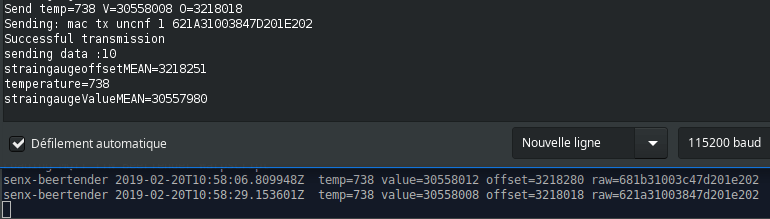
Here the raw payload decoded by Warp 10: A1FC30006B47D201DD02. Temperature is 733, 0x2DD. The end of my payload is DD02. I have an endianness problem! Note for next Warp 10 release: add functions to easily reverse bytes arrays. Here is the WarpScript that decodes the MQTT messages from our connected BeerTender:
// subscribe to the BeerTender topic, attach a warpscript macro callback to each message
// the macro read TheThingNetwork message to extract the payload and process it.

'Loading MQTT TTN BeerTender Warpscript' STDOUT

{
  'host' 'eu.thethings.network'
  'port' 1883
  'user' 'senx-sensors'
  'password' 'myappkey'
  'clientid' 'Warp10'
  'topics' [ 'senx-sensors/devices/senx-beertender/up' ]
  'timeout' 20000
  'parallelism' 1
  'autoack' true
  'macro' <%
    //in case of rx timeout, the macro is called with NULL on the stack to flush buffers if any.
    'message' STORE
    <% $message ISNULL ! %>
    <%
      $message MQTTPAYLOAD 'ascii' BYTES-> JSON-> 'TTNmessage' STORE
      $TTNmessage 'payload_raw' GET B64-> ->HEX 'rawpayload' STORE
      //bff830001d48d201db02 string
      $TTNmessage 'metadata' GET 'time' GET TOTIMESTAMP 'ts' STORE
      $TTNmessage 'dev_id' GET 'sensorID' STORE

      //little helper macro to reverse bytes in the string representation
      <%
        's' STORE
        '' // push an empty string on the stack
        $s SIZE 2 -
        0
        <% 2 - %> //iterate from string size - 2 to 0, step -2
        <%
          'i' STORE
          $s $i 2 SUBSTRING + //concatenate with the string on the stack
        %> FORSTEP
      %> 'reverseEndianness' STORE

      $rawpayload 0 8 SUBSTRING @reverseEndianness FROMHEX 'offset' STORE // first 8 characters to long
      $rawpayload 8 8 SUBSTRING @reverseEndianness FROMHEX 'value' STORE // next 8 characters to long
      $rawpayload 16 4 SUBSTRING @reverseEndianness FROMHEX 'temperature' STORE // last 4 characters to long
      $sensorID ' ' +
      $ts ISO8601 + ' ' +
      ' temp=' + $temperature TOSTRING +
      ' value=' + $value TOSTRING +
      ' offset=' + $offset TOSTRING +
      ' raw=' + $rawpayload +
      STDOUT // print to warp10.log
    %> IFT
  %>
}
Uploading data in Warp 10 is just a few more lines of WarpScript:
//my local write token
'vQbBxsWwjtadYyr0jajvlK5QgdaeRxtbpuo2vsdbOCRXmspZ' 'wt' STORE
NEWGTS 'beertender.rawtemperature' RENAME
$ts NaN NaN NaN $temperature ADDVALUE
$wt UPDATE

NEWGTS 'beertender.rawvalue' RENAME
$ts NaN NaN NaN $value ADDVALUE
$wt UPDATE

NEWGTS 'beertender.rawoffset' RENAME
$ts NaN NaN NaN $offset ADDVALUE
$wt UPDATE
Final Check calibration
On my screen, I have the Arduino output and the Warp 10 logs: perfect match.
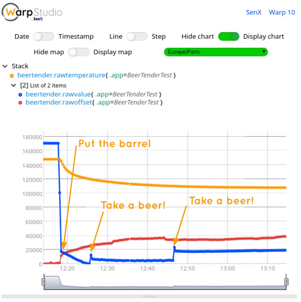
12h15: Lunch, time for a beer! I put an already chilled BeerTender barrel in our newly connected device, and wait a few minutes. Then I served one and another one for a. I wrote a quick WarpScript to get data, remove the offset, multiply temperature to have in on the same scale:
// @preview gts
//read local data from BeerTender
'C5UrCikHoK8axjnweNrA24v1aPSHEn97v0AkTFfnQPW9S1BvFf7FVJC3NHePk' 'rt' STORE

[ $rt '~beertender.(rawvalue|rawoffset)' {} NOW MINLONG ] FETCH

<%
  DROP
  'g' STORE
  $g
  [ $g bucketizer.min 0 0 1 ] BUCKETIZE
  0 GET VALUES 0 GET  -
%> LMAP

// [ SWAP [] reducer.sum ] REDUCE
// sum value and offset ? maybe ?

[ $rt 'beertender.rawtemperature' {} NOW MINLONG ] FETCH
0 GET 200 *
Great, the result is here!
Further work: calibrate the temperature sensor and try to guess the temperature law to correct the strain gauge results.
Conclusion
In a few days, I discovered LoRa, MQTT, I reversed engineered the BeerTender weight sensor, and now I have raw data flowing into the Warp 10 time series database. Advanced analytics are now possible!
I hope you also learned a lot while reading this article!
We encourage you to check out Warp 10 and its multiple plugins, enabling you to do advanced IoT applications without having to deploy multiple tools.
If you like electronics, the IoT, code … and beer, ping us, SenX is hiring!
| Next step: learn how to build a BeerTender Dashboard with Warp 10 and Grafana! |
Read more
Warp 10 Docker Image - Next Generation
Covid Tracker built with Warp 10 and Discovery
Discovery Tips&Tricks #1 - Synchronization of zoom and focus between charts

Electronics engineer, fond of computer science, embedded solution developer.